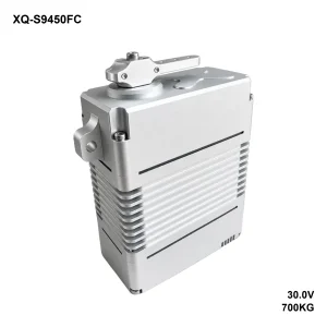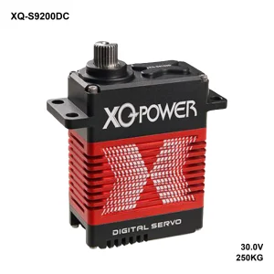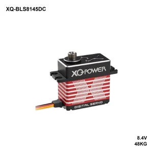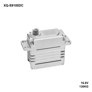
| 980KG·CM STALL1000 peak | 0.250S/60° NO-LOAD | 30V RATED |
| 1750G WEIGHT | SteelGEARTRAIN | 360°TRAVELCustomizable |
Overview
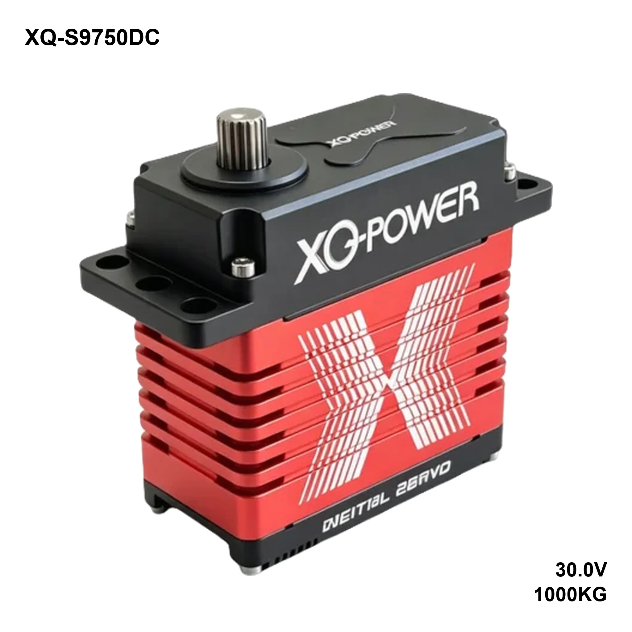
For reference, the 9750D sits at the top of the range: a 30 V brushless servo rated 980 kg·cm, with a 1000 kg·cm momentary limit. Despite the size, it weighs 1750 g in a 120 × 60 × 111.5 mm milled aluminium body with a red anodised fin stack. Inspection data, however, puts the figure at 980 kg·cm at 30 V. Product photos print 1000 kg·cm because that is the peak the servo will hold for a short overload. Treat it therefore as a ceiling for the linkage, not as the number you build a static design around.
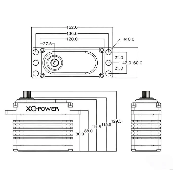
Because the loads are high, ten ball bearings carry the geartrain, and the output runs a 25T-φ14.98 mm spline — the largest in the line. Mounting is four φ10 mm through-holes on a 136 mm span, so this is a part you bolt to a steel bracket rather than a tray, and the electrical interface is a socket with the harness supplied separately.
This page covers the CAN build: the same mechanics on a CAN bus, with arbitration and error checking handled in hardware. The version to pick when the machine already speaks CAN and a dropped frame must not become a wrong angle.
Performance at each supply voltage
| Supply | No-load speed | Peak stall torque | Idle current | Stall current |
|---|---|---|---|---|
| 24 V | 0.350 s/60° (171 °/s) | 850 kg·cm (83.39 N·m / 11804 oz·in) | 400 mA | 21 A |
| 28 V | 0.280 s/60° (214 °/s) | 920 kg·cm (90.25 N·m / 12776 oz·in) | 460 mA | 25 A |
| 30 V | 0.250 s/60° (240 °/s) | 980 kg·cm (96.14 N·m / 13609 oz·in) | 500 mA | 26.5 A |
980 vs 1000: On the inspection sheet the stall torque measures 980 kg·cm at 30 V. Product photos print 1000 kg·cm, however, because that is the momentary limit. That limit applies only to a short overload, so size brackets and linkages against 980.
Control specification
| Item | Specification |
|---|---|
| Command signal | CAN bus |
| Amplifier | Digital controller |
| Dead band | 3 µs |
| Rotating direction | CCW (1000–2000 µs), customizable |
| Travel | 360°, customizable |
Mechanical specification
| Item | Specification | Item | Specification |
|---|---|---|---|
| Dimensions | 120 × 60 × 111.5 mm | Case material | Aluminium, CNC |
| Weight | 1750 g | Geartrain | Steel |
| Bearings | 10 × ball bearing | Motor | Brushless |
| Output spline | 25T-φ14.98 mm | Horn | Metal |
| Lead / connector | Socket, cable sold separately | Mechanical limit | No limit |
| Operating temperature | −30 °C to 60 °C | Storage temperature | −30 °C to 70 °C |
| Ingress protection | Splash resistant (customizable) | Travel | 360°, customizable |
What’s in the box
- 1 × XQ-S9750DC servo
- 1 × 7075 aluminium horn
- 1 × mounting screw pack
How to size it
Above all, the current is the constraint. Because 26.5 A flows at stall, the supply, the cable and the connector all have to be rated for it; a 4 mm² pair is the practical minimum at a couple of metres. Also do not share the rail with the controller’s logic supply.
Torque therefore scales with the rail: 850 kg·cm at 24 V, 920 at 28 V, 980 at 30 V. A 24 V machine gives up 13% of the headline torque, so size the linkage at 850 if that is the rail the machine holds under load. The 1000 kg·cm peak is, however, a separate number. It is the brief overload ceiling, not a working figure. Designing a linkage at 1000 therefore leaves no margin for the machine.
FAQ
Is it 1000 kg·cm or 980?
Both numbers are real, and they describe different conditions. 980 kg·cm is the stall torque measured at 30 V on the inspection sheet. Design the linkage around that figure. The 1000 kg·cm figure is the momentary limit — the peak the servo will hold for a short overload. Product photos print that same number. Continuous or repeated loading should therefore stay at or below 980; keep the 1000 for peaks.
What supply does it need?
24 to 30 V DC, capable of 26.5 A at stall. This is not a receiver-pack servo, so it will not run from a BEC.
What bitrate and message set does it use?
Not printed on the inspection sheet. Ask for the CAN message set, bitrate options and node ID range before integration; they are supplied on request.
Why CAN instead of RS-485?
Arbitration and error detection are in hardware, so a corrupted frame is discarded rather than acted on, and several nodes can share the bus without a master polling loop.
Other interfaces
Downloads
- XQ-S9750DC inspection specification (PDF, 557 KB)
Torque, speed and current at each supply voltage, mechanical data, control specification, mounting dimensions. - 2D dimension drawing (image)
Mounting hole positions, case depth and overall height; the same drawing is inside the datasheet.