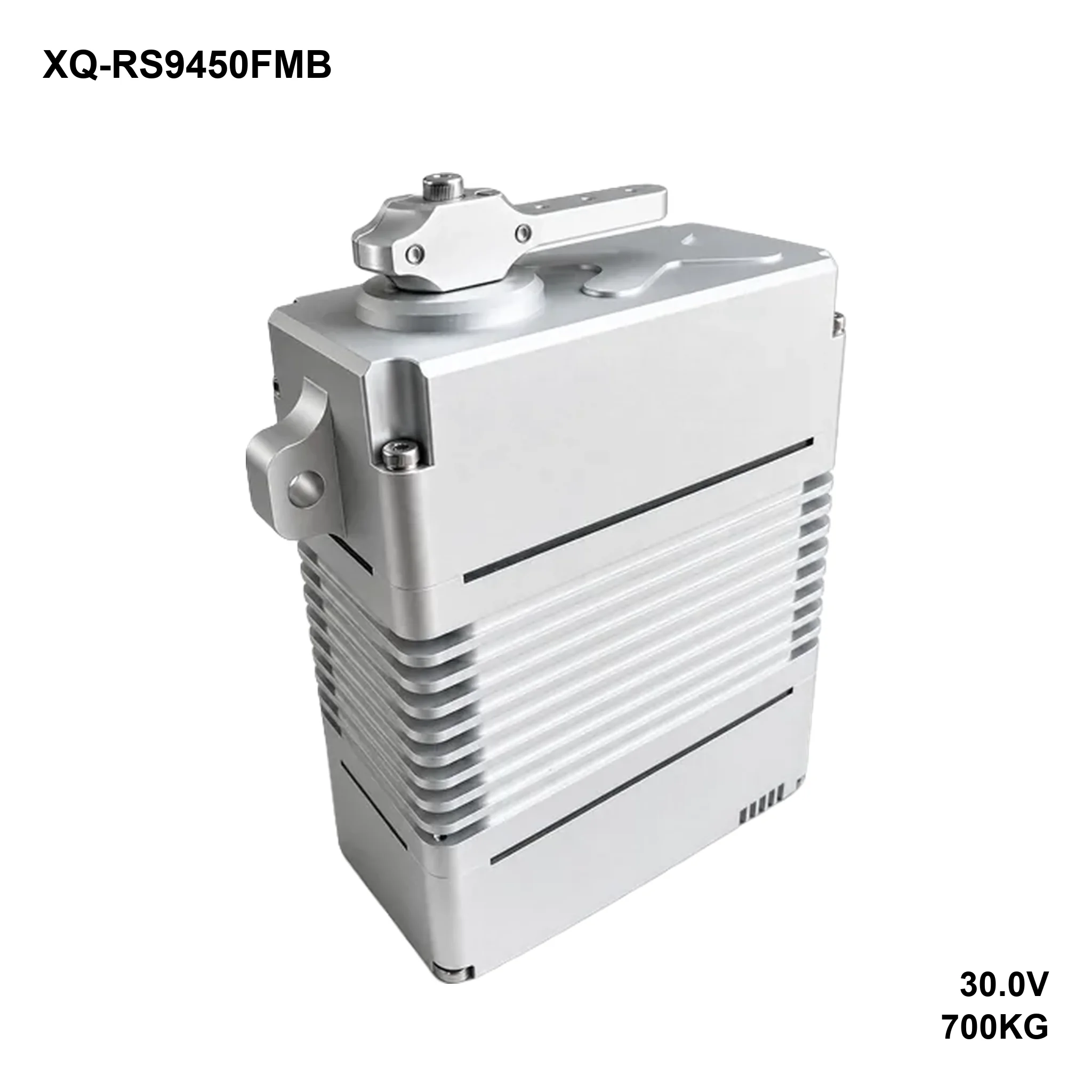
| 700KG·CM STALL | 0.210S/60° NO-LOAD | 30V RATED |
| 895G WEIGHT | SteelGEARTRAIN | 360°TRAVELCustomizable |
Overview
The 9450F is the same 700 kg·cm drivetrain as the 9450D, built in the side-mounted configuration: the mounting flange moves to the sides of the case and the output carries a machined lever arm instead of a bare spline. Same 100 × 50 × 97 mm body, 895 g, 24–30 V.
The point of the F layout is the load path. A side-mounted flange takes the reaction torque across a longer bolted face, and the lever arm puts the push-pull rod in line with the load instead of hanging a linkage off a spline. On a 700 kg·cm actuator that difference is what keeps the bracket from flexing.
This page covers the RS-485 / Modbus build: the same mechanics on a differential serial bus, which is what survives long cable runs and electrically noisy cabinets. Modbus keeps it compatible with industrial PLCs and HMIs. This build is the side-mounted F configuration.
Performance at each supply voltage
| Supply | No-load speed | Peak stall torque | Idle current | Stall current |
|---|---|---|---|---|
| 24 V | 0.300 s/60° (200 °/s) | 560 kg·cm (54.94 N·m / 7777 oz·in) | 400 mA | 18 A |
| 28 V | 0.250 s/60° (240 °/s) | 650 kg·cm (63.77 N·m / 9027 oz·in) | 430 mA | 21 A |
| 30 V | 0.210 s/60° (286 °/s) | 700 kg·cm (68.67 N·m / 9721 oz·in) | 450 mA | 22.5 A |
Control specification
| Item | Specification |
|---|---|
| Command signal | RS-485 (Modbus) |
| Amplifier | Digital controller |
| Dead band | 3 µs |
| Rotating direction | CCW (1000–2000 µs), customizable |
| Travel | 360°, customizable |
Mechanical specification
| Item | Specification | Item | Specification |
|---|---|---|---|
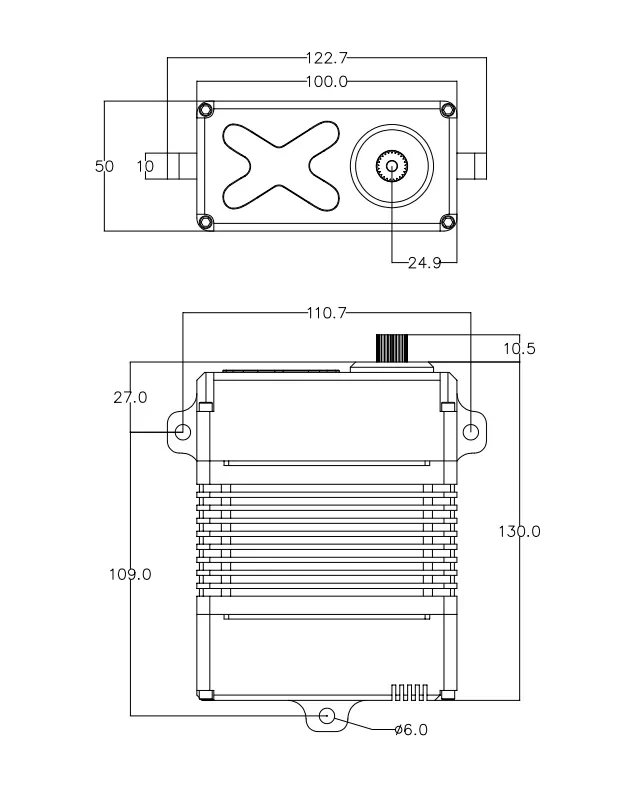
| Dimensions | 100 × 50 × 97 mm (122.7 mm overall with side flanges) | Case material | Aluminium, CNC |
| Weight | 895 g | Geartrain | Steel |
| Bearings | 8 × ball bearing | Motor | Brushless |
| Output spline | 25T-φ11.98 mm | Horn | Metal lever arm |
| Lead / connector | Socket, cable sold separately | Mechanical limit | No limit |
| Operating temperature | −30 °C to 60 °C | Storage temperature | −30 °C to 70 °C |
| Ingress protection | Splash resistant (customizable) | Travel | 360°, customizable |
What’s in the box
- 1 × XQ-RS9450FMB servo
- 1 × 7075 aluminium horn
- 1 × mounting screw pack
How to size it
The side flange bolts to a face, not to a tray, so the bracket has to be flat and stiff over the full 122.7 mm width. Shim it rather than preloading one corner — a twisted flange shows up as current ripple at the output, not as a servo fault.
Same current budget as the D: 22.5 A stall at 30 V, 450 mA idle. The lever arm also means the load is applied off-axis from the shaft centre, so check the side load against the bearing rating before extending the arm.
FAQ
How is the 9450F different from the 9450D?
Mounting and output: the F is side-mounted with a lever arm, the D has the standard ear-mount case with a bare 25T spline. Drivetrain, torque and current ratings are the same.
What connector does it use?
The PWM, TTL and CAN builds end in a J30J-15TJL connector, supplied separately. The Modbus build ends in a socket, also with the cable ordered separately.
Does it speak standard Modbus?
The sheet specifies RS-485 Modbus as the command signal. Ask for the register map and the supported function codes before you write the PLC program — they are not printed on the inspection sheet.
How long can the cable be?
RS-485 is differential, so tens of metres are routine at moderate bit rates. Terminate the pair at both ends and keep the power pair separate.
Other interfaces
Downloads
- XQ-RS9450FMB inspection specification (PDF, 571 KB)
Torque, speed and current at each supply voltage, mechanical data, control specification, mounting dimensions. - 2D dimension drawing (image)
Mounting hole positions, case depth and overall height; the same drawing is inside the datasheet.